48 V fuel injector pulser: circuit design, PCB, firmware and test report
Services: PCB design, PCB assembly, firmware, testing Year: 2020 Client: A Canadian fuel injector service business
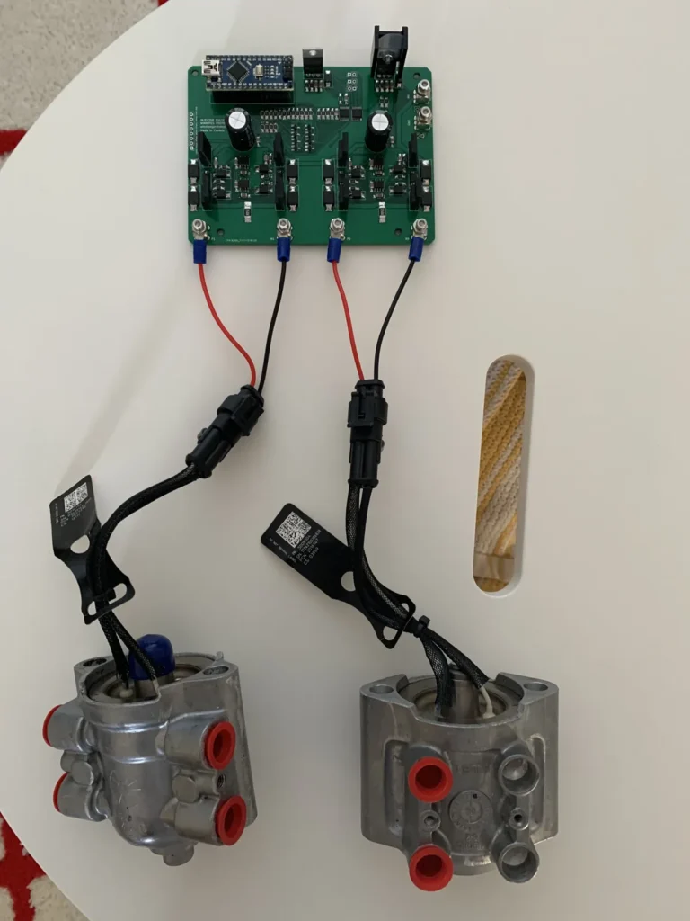
A fuel injector service shop needed a bench circuit that could fire injectors with controlled 48 V pulses in both directions. We designed the circuit, laid out and assembled the board, wrote the firmware and delivered it with measured waveforms and operating instructions.
The challenge
The shop services injectors and wanted its own pulser to drive them on the bench. The circuit had to switch 48 V through an inductive load, deliver both forward and reverse pulses, and run two injectors from one board.
What we did
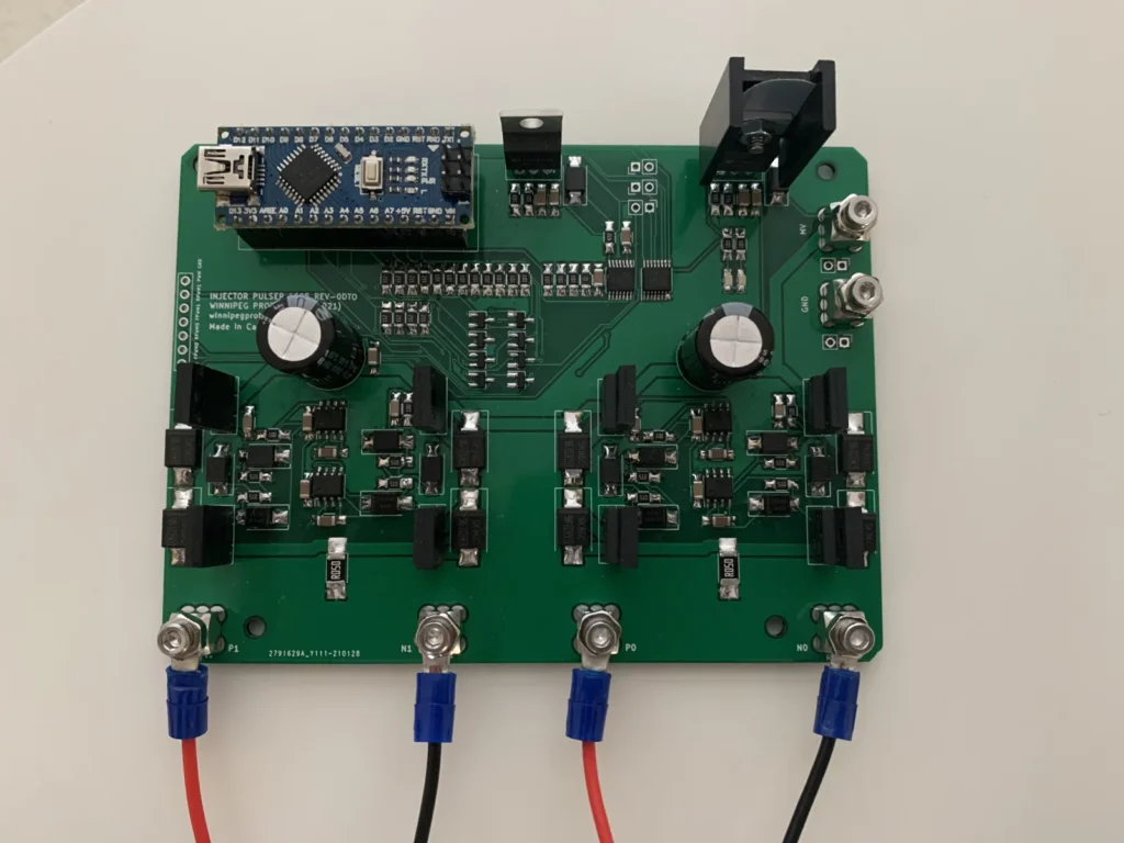
Developed the schematic through several reviewed revisions, with separate bridge and gate driver stages for the forward and reverse pulses.
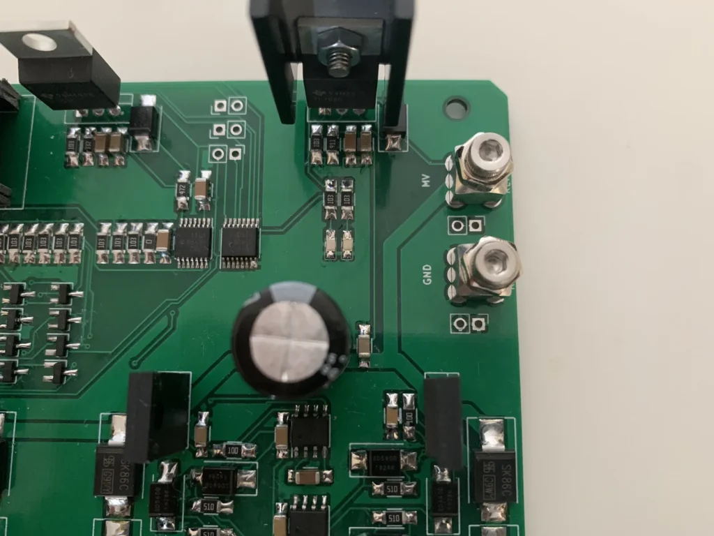
Laid out a two-channel PCB with bolted terminals for the supply and injector leads, then assembled it in-house.
Wrote microcontroller firmware to time the pulses, refined over three releases between May and September 2020.
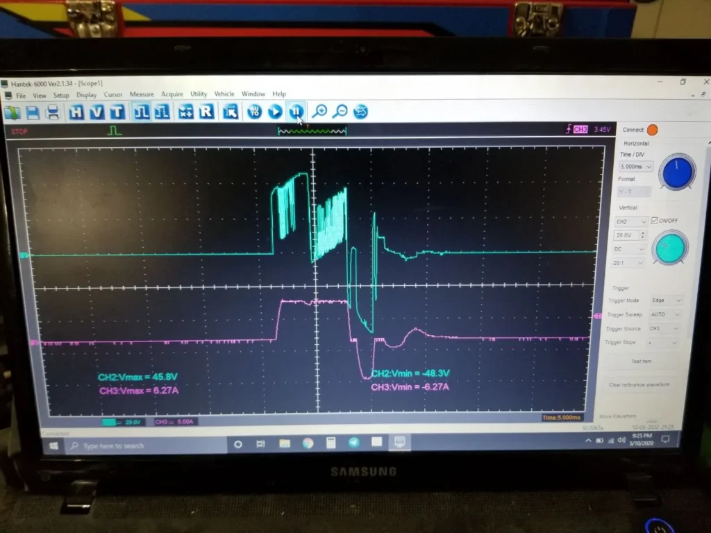
Measured the forward and reverse 48 V pulses and injector current on an oscilloscope with a current probe, and documented the waveforms in an eight-page results report.
Wrote operating instructions covering the 48 V supply connection, injector wiring and safe handling.
The result
The client received an assembled, tested two-injector pulser board, the waveform report and the operating instructions.
Tools and methods: Schematic capture and PCB layout, Arduino-based firmware, oscilloscope and current probe
Have a similar project?
Tell us what you need built, scanned or designed and we will reply with a scope and a quote.